We’re going to add a router between two independent networks in Packet Tracer.
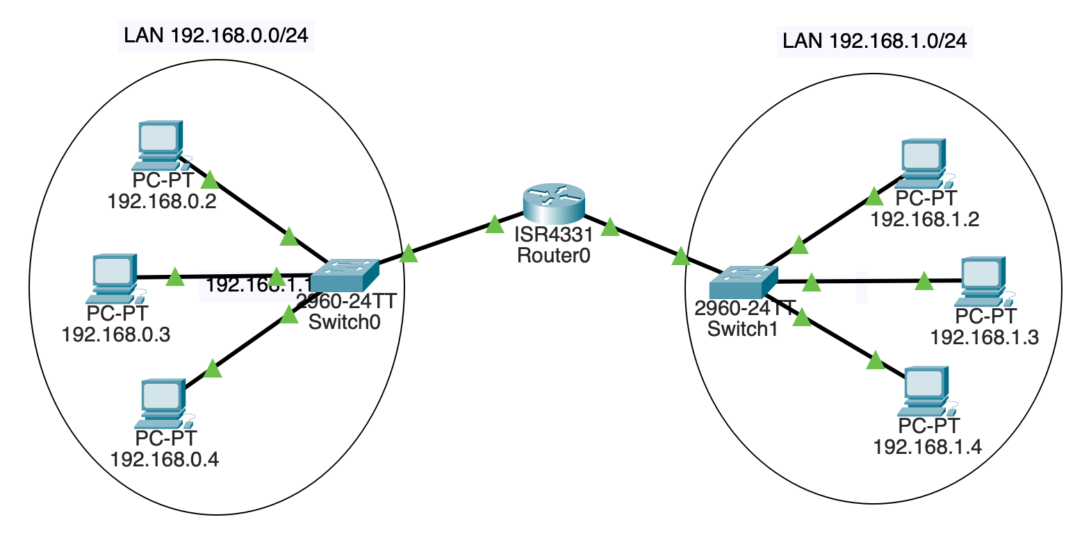
The goal will be something that looks like this:
First of all, build two separate LANs. Each will have three PCs and a 2960 switch like before.
The left subnet will be 192.168.0.0/24. The right subnet will be 192.168.1.0/24.
Assign the left PCs the IP addresses on their FastEthernet0 interfaces:
192.168.0.2192.168.0.3192.168.0.4Assign the right PCs the IP addresses on their FastEthernet0 interfaces:
192.168.1.2192.168.1.3192.168.1.4All of them have subnet mask 255.255.255.0.
Connect the left PCs to one switch on any unused FastEthernet ports. Connect the right PCs to the other switch in the same way.
At this point, you should have two separate LANs.
Hit the fast-forward button if all the links aren’t green yet. If they stay red, something is wrong–double-check your settings.
For sanity, make sure 192.168.0.2 can ping the other two machines on its LAN. And make sure 192.168.1.3 can ping the other two machines on its LAN.
The router is going to route traffic between these two networks.
Click the “Network Devices” icon in the lower left. Then click “Routers” in the bottom left. Then drag a 4331 router in between the two.
This router is going to be connected to both switches. Each “side” of the router will have a different IP address.
We’re going to connect some wires here, but the link won’t come up yet. We’ll deal with that in a minute.
On the switch on LAN 192.168.0.0/24, use a Copper Straight-Through connector to connect the switch’s GigabitEthernet0/1 port to the router’s GigabitEthernet0/0/0 port.
On the switch on LAN 192.168.1.0/24, use the same type of connector to connect the switch’s GigabitEthernet0/1 port to the router’s GigabitEthernet0/0/1 port.
Note this is a different port on the router than the other switch is connected to! Both switches are plugged into different ports on the router.
We have the hardware in place now, but we don’t yet have any IP addresses assigned on the router. So let’s do that.
In the “Config” for the router, choose the GigabitEthernet0/0/0 interface and give it the IP address 192.168.0.1–it’s now part of the 192.168.0.0/24 subnet. While you’re here, click the “On” checkbox to power the port. This should bring up the connection and get you the green arrows.
Then go to the GigabitEthernet0/0/1 interface and give it the IP address 192.168.1.1–it’s now part of the 192.168.1.0/24 subnet. While you’re here, click the “On” checkbox to power the port.
Let’s try pinging the router. Go to any PC on the 192.168.0.0/24 LAN and trying pinging 192.168.0.1 (the router). It should reply.
Then go to any PC on the 192.168.1.0/24 subnet and try pinging 192.168.1.1. It should reply.
Now the ultimate test: get a console on PC 192.168.0.2 and try to ping 192.168.1.2 on the other subnet!
It… doesn’t work!
Why?
All the computers need to know two things:
We’ve put the subnet in, but not the default gateway.
For all the PCs on the 192.168.0.0/24 subnet, go into the “Config”, then choose the “Global” sidebar item. Enter 192.168.0.1 (the router!) in the “Default Gateway” field.
Do the same for all the PCs on the other subnet, except enter 192.168.1.1 as the default gateway.
Now you should be able to ping any PC from any other PC!
If you can’t, try pinging just on one LAN to make sure it works. And ping the router on that LAN to make sure that works.